I have been building moirestrain, a small NumPy-first Python package for sampling moire analysis of periodic grating images.

The original scope was planar measurement: estimate phase from reference and deformed grating images, convert the phase difference to in-plane displacement, and calculate small strain fields.
Recently I added an experimental extension for known 3D surfaces. This is not a full 3D sampling moire system. It does not reconstruct an unknown surface from images. Instead, it answers a narrower question:
If the 3D surface geometry is already known, can the 2D sampling moire displacement field be lifted to 3D tangent displacement and surface strain?
The answer, at least for synthetic tests, is yes.
Repository
Package:
moirestrainMain ideas already implemented:
- phase-shifted sampling moire image generation,
- wrapped phase estimation,
- reference/deformed phase difference,
- displacement and strain estimation,
- square-marker grid analysis,
- planar rectification,
- and now a known-surface post-processing layer.
Reminder: What Sampling Moire Does Here
For each analysis direction, the implementation creates a stack of phase-shifted moire images from one grating image:
- choose a sampling offset,
- sample pixels every
periodpixels, - linearly interpolate the sampled image back to the original image grid.
The stack is then treated as a set of equally phase-shifted images:
I_k = a + b \cos\left(\phi + \frac{2\pi k}{N}\right)and the wrapped phase is estimated from the first Fourier component:
\phi =
\mathrm{atan2}\left(
-\sum_{k=0}^{N-1} I_k \sin\frac{2\pi k}{N},
\sum_{k=0}^{N-1} I_k \cos\frac{2\pi k}{N}
\right).
The displacement component is then calculated from the phase difference:
u = \frac{\Delta\phi}{2\pi}pwhere p is the grating pitch.
What Changed
The new layer introduces a sampled surface geometry:
surface_points[y, x] = (X, Y, Z)The existing 2D pipeline still estimates displacement in surface-parameter coordinates:
u: displacement along the x-parameter direction
v: displacement along the y-parameter direction
The new surface layer converts those fields to 3D tangent displacement:
from moirestrain import SurfaceGeometry, tangent_displacement, surface_strain

surface = SurfaceGeometry(surface_points)

disp3d = tangent_displacement(
    surface,
    result.x.displacement,
    result.y.displacement,
)

strain = surface_strain(surface, disp3d, smooth_window=17)
Conceptually:
reference/deformed grating images
  -> sampling moire phase analysis
  -> u, v in surface-parameter coordinates
  -> 3D tangent displacement on known surface
  -> surface strain
Important Scope Limit
This is not the same as a full 3D sampling moire method from the literature.
Many reported 3D sampling moire methods include stereo vision, camera calibration, phase matching, or phase-to-depth calibration. They estimate 3D shape and 3D displacement from images.
This implementation currently assumes that the 3D surface grid is already known or separately measured.
So the safe description is:
a known-surface extension layer for a 2D sampling moire pipeline
not:
a complete unknown free-surface reconstruction method.
Synthetic Experiments
I added three experiments.
1. Ideal Sinusoidal Gratings
Two separated sinusoidal grating pairs are generated, one for the x direction and one for the y direction. There is no blur and no noise.
Result:
| metric | value |
|---|---|
| mean u error | 5.252e-06 px |
| mean v error | 1.422e-06 px |
| mean 3D displacement error | 5.517e-06 |
| mean surface exx error | 2.176e-08 |
| mean surface shear error | 1.016e-08 |
This confirms that the known-surface lifting step itself is working.
2. Camera-Like Sinusoidal Gratings
The same sinusoidal setup is used, but with:
- 4x supersampling,
- box blur window 3,
- Gaussian noise standard deviation 0.002.
Result:
| metric | value |
|---|---|
| mean u error | 3.559e-03 px |
| mean v error | 3.761e-03 px |
| mean 3D displacement error | 5.885e-03 |
| mean surface exx error | 7.605e-05 |
| mean surface shear error | 2.316e-04 |
The displacement remains fairly accurate, but strain is more sensitive because it differentiates the displacement field. Smoothing before surface-strain differentiation is important.
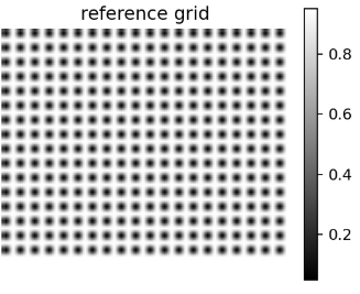
3. Square-Marker Grid on a Known Surface
This is closer to the original target of moirestrain: a white grid with black square markers. The grid is synthesized in surface-parameter coordinates and then analyzed with analyze_grid.
Setup:
- shape: 128 x 160,
- period: 8 px,
- known surface amplitude: 7,
- 32x supersampling,
- box blur window 3,
- no added noise.
Result:
| metric | value |
|---|---|
| mean u error | 5.590e-03 px |
| mean v error | 1.044e-02 px |
| mean 3D displacement error | 1.308e-02 |
| mean surface exx error | 8.143e-05 |
| mean surface shear error | 1.497e-04 |
The square-marker case is harder than separated sinusoidal gratings, but the known-surface conversion remains stable. Most of the error appears to come from phase/displacement extraction from the square-marker image, not from the 3D surface conversion.
Small Sweep
I also ran a small sweep over surface amplitude, blur, and noise.
| surface amp | blur | noise | 3D disp MAE | gamma_xy MAE |
|---|---|---|---|---|
| 0 | 1 | 0 | 7.595e-06 | 3.211e-09 |
| 0 | 1 | 0.002 | 4.422e-03 | 2.503e-04 |
| 0 | 3 | 0 | 1.540e-04 | 1.082e-05 |
| 0 | 3 | 0.002 | 5.493e-03 | 3.098e-04 |
| 7 | 1 | 0 | 7.820e-06 | 3.588e-08 |
| 7 | 1 | 0.002 | 4.622e-03 | 2.489e-04 |
| 7 | 3 | 0 | 1.565e-04 | 1.091e-05 |
| 7 | 3 | 0.002 | 5.741e-03 | 3.078e-04 |
In this synthetic setup, noise and blur dominate more than the surface amplitude itself.
Literature Position
There are already research papers on 3D sampling moire methods. Examples include:
methodology.
- binocular-vision-based 3D sampling moire for complex shape measurement,
- 3D sampling moire for shape and deformation using stereo vision,
- rotating tire shape and strain measurement by sampling moire,
- single-camera calibrated 3D displacement measurement based on moire
Compared with those methods, this implementation is much simpler. It does not yet solve:
- stereo correspondence,
- camera calibration,
- unknown surface reconstruction,
- phase matching between camera views,
- out-of-plane displacement estimation from image data alone.
That is intentional for now. The purpose of this branch is to create a clean computational layer:
2D sampling moire displacement
  + known surface geometry
  -> 3D tangent displacement and surface strain
Reproduction
Example commands:
PYTHONPATH=src python examples/freeform_surface_experiment.py \
  --output-dir /tmp/moirestrain-result/sinusoidal_ideal \
  --shape 96,112 \
  --period 8 \
  --supersample 1 \
  --blur-window 1 \
  --noise-std 0 \
  --strain-smooth-window 17 \
  --no-figure
PYTHONPATH=src python examples/freeform_surface_experiment.py \
--output-dir /tmp/moirestrain-result/sinusoidal_camera \
--shape 96,112 \
--period 8 \
--supersample 4 \
--blur-window 3 \
--noise-std 0.002 \
--strain-smooth-window 17 \
--no-figurePYTHONPATH=src python examples/freeform_square_grid_experiment.py \
--output-dir /tmp/moirestrain-result/square_grid \
--shape 128,160 \
--period 8 \
--surface-amplitude 7 \
--supersample 32 \
--blur-window 3 \
--noise-std 0 \
--strain-cycles 8 \
--no-figureWhat Comes Next
The next natural step is to move closer to the literature:
- calibrated stereo or multi-view input,
- phase extraction in each camera view,
- phase-based correspondence,
- triangulation of the surface,
- deformation tracking between reference and deformed states.
For now, the known-surface layer is useful as a controlled stepping stone. It separates the geometry problem from the phase-estimation problem and gives a simple way to validate surface displacement and strain calculations.